Follow the steps below to setup your measurement point from the instrument directly on its Web Interface or HMI.
¶ Step 0: Prerequisite
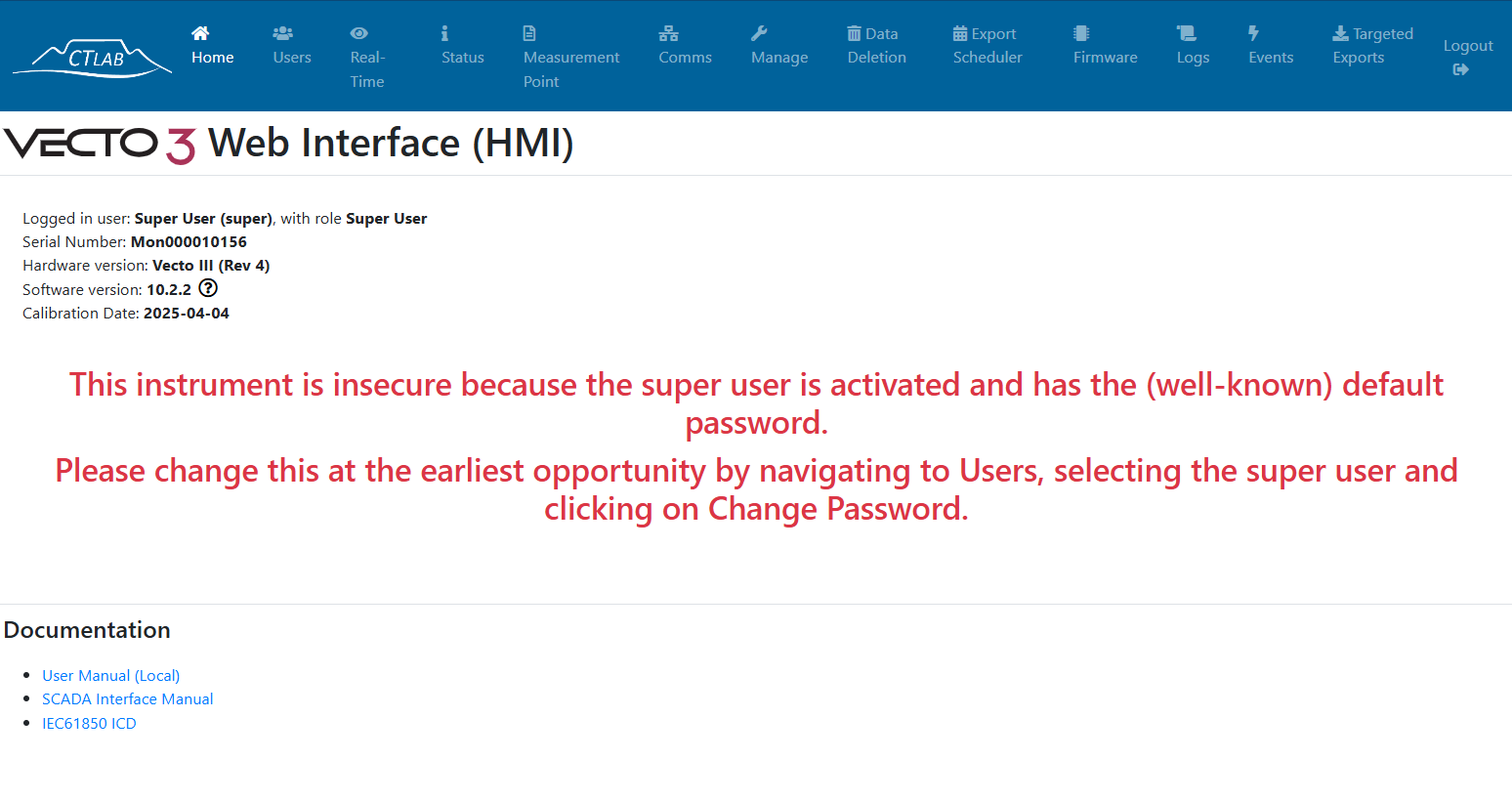
Firstly you have to be logged-in to the HMI and have the HMI enabled on your instrument. For more information on how to activate the HMI click here.
¶ Step 1: Navigate to the "Measurement Point" Tab
Click on the "Measurement Point" tab on the top of the HMI windows to navigate to the measurement point setup page.
¶ Step 2: Details Section
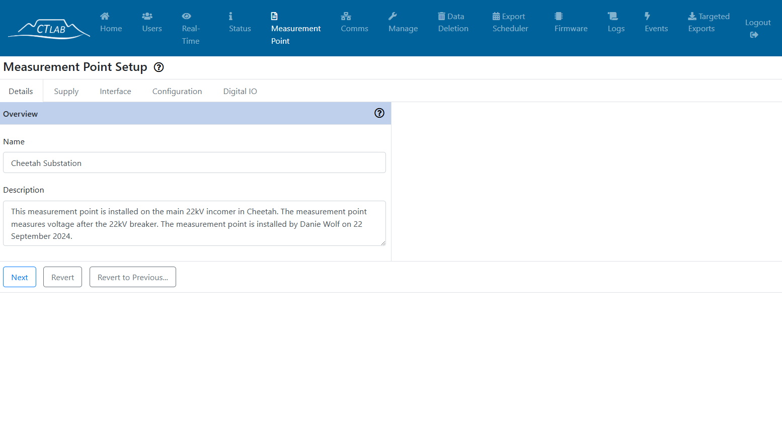
Select a Name for Your Measurement Point:
The name should ideally be:
-
Descriptive and clear, such as the location and type of measurement (e.g., "Cheetah Substation Incomer" or "Hospital Transformer 1").
-
Consistent in naming convention, especially if you're managing a large fleet (e.g., "SiteName_Equipment_Function").
-
Used to easily recognize and manage the MP later within the platform, graphs, and reports.
-
Each name must be unique within your organization’s VGOS environment to avoid confusion or errors.
Enter a Description of the Measurement Point:
The description provides contextual information about the MP and helps other users understand:
-
What is being measured (e.g., voltage at the incoming feeder of a substation),
-
Where it's located (e.g.site name, building),
-
Any special notes (e.g., "This point is used for monitoring harmonics", or "backup generator output").
This field is especially useful for documentation, collaboration, and audits.
Tip: Include relevant technical specs or purpose to make the MP easy to identify without needing to check setup details.
¶ Step 3: Supply Section
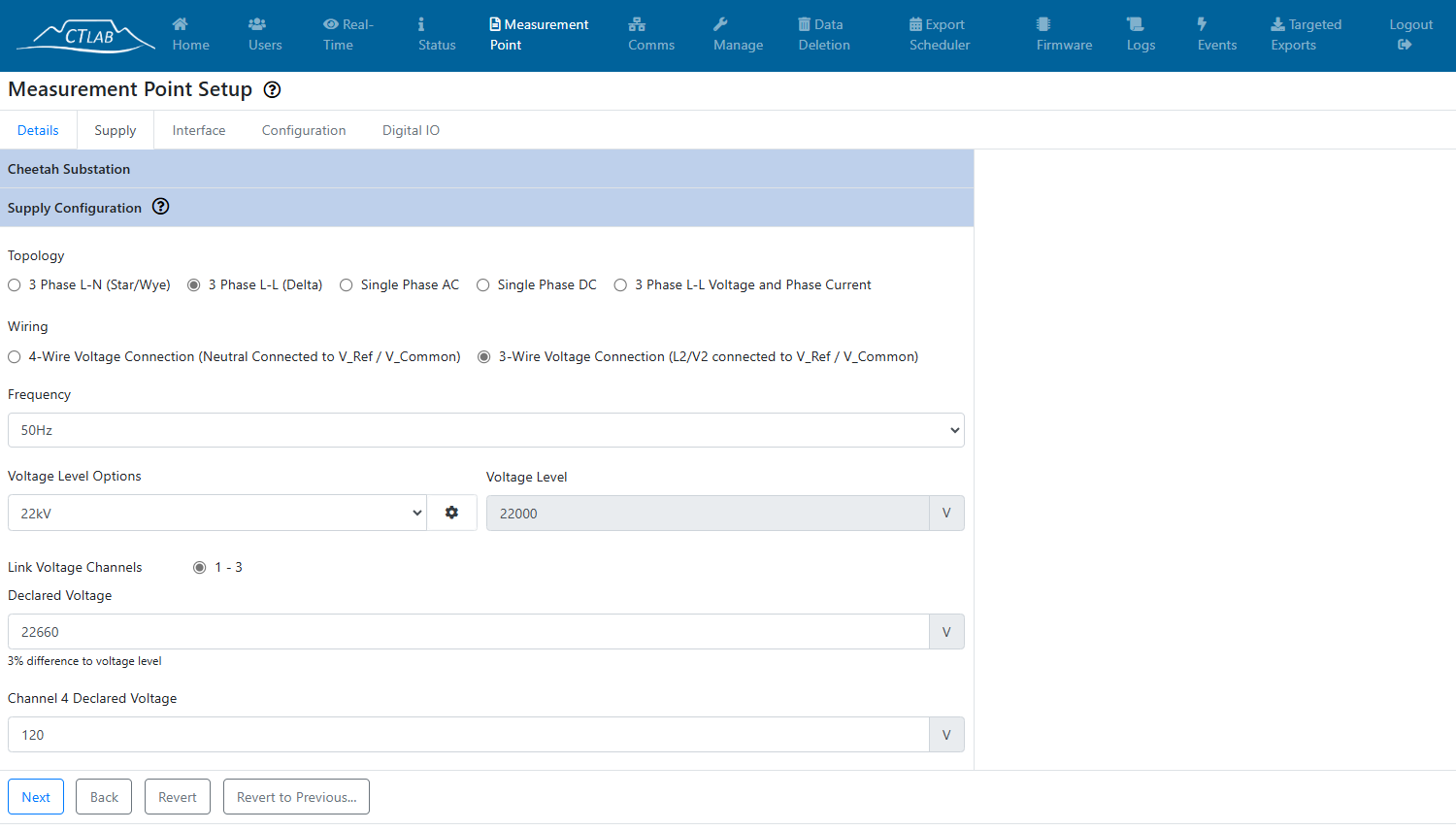
In this step, the physical supply parameters have to be populated. Follow the sub-steps below to enter all the required details of the supply section of the measurement point.
Step 3.1: Select your network typology
This is the type of topology you want to measure in and record. If you have a "delta" wiring topology (3-Wire) then you must choose "3 Phase L-L (Delta)".
If you have a 4-Wire systems (with a neutral conductor connected to the reference input) then you can either choose "3 Phase L-L (Delta)" or "3 Phase L-N (Star/Wye)"
See the Installation Guide for further details on the two types of voltage installation topologies.
Step 3.2: Select your wiring topology
This is how you installed your measurement. Again, see the Installation Guide for further details on the two types of voltage installation topologies.
Step 3.3: Select your frequency
Nominal frequency of your network.
Step 3.4: Select your voltage level
The nominal voltage level of your network.
Step 3.5: Select the declared voltage
This is the declared (contractually agreed) voltage of your system.
Step 3.6: Click the "Next" button
¶ Step 4: Voltage Measurement Interface Parameters
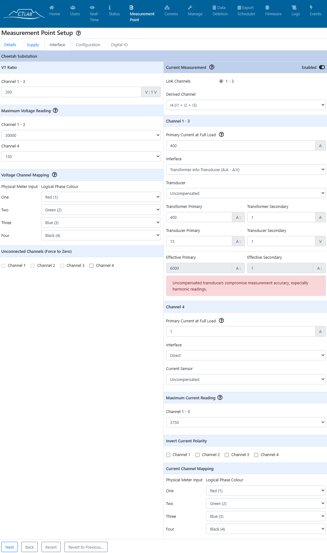
In this step, further parameters of the physical connection such as VT and CT ratios have to be populated. Follow the sub-steps below to enter all the required details of the interface section of the measurement point.
Step 4.1: Enter your VT Ratio
This is the ratio of any VT connected to the voltage inputs.
Ex: 22kV:110V is equal to 200V:1V
Step 4.2: Select the maximum voltage that will be measured
Select the maximum voltage in RMS that will be measured to optimize the dynamic range of the measurement.
Step 4.3: Change the voltage channel mapping
Only change this settings if it is really necessary and you fully understand what this means.
Step 4.4: Mark if there are any unconnected channels
This setting will force the respective channel to 0 and ensure that no floating voltage is measured.
¶ Step 5: Current Measurement Interface Parameters
Step 5.1: Select is you are deriving any channels
If you are using a delta system, either of the three channels can be derived from any of the other two.
Step 5.2: Enter the primary current at full load
Used to calculate Total Demand Distortion (TDD) and % full scale current.
Step 5.3: Choose current measurement interface
Current Connection Interface Topologies:
- Transformer (A:A)
- Transducer (A:V)
- Transformer into Transducer (A:A > A:V)
If you have chosen one of the two options with a transducer, you have the option to specify the transducer to apply a harmonic compensation curve to compensate for some non-linearity. This is optional and if you are using a transducer which is not on the list, leave the field on "uncompensated".
Step 5.4: Choose Maximum Current Reading
Select the maximum current in RMS that will be measured to optimize the dynamic range of the measurement.
Step 5.5: Select Current Polarity
If you have inverted currents it can be corrected in software by selecting the relevant channels here.
Step 5.6: Change the current channel mapping
Only change this settings if it is really necessary and you fully understand what this means.
¶ Step 6: Recording Configuration
In this step, continuous data recording options (left hand side of the screen) are selected and event monitors (right hand side of the screen) is configured.
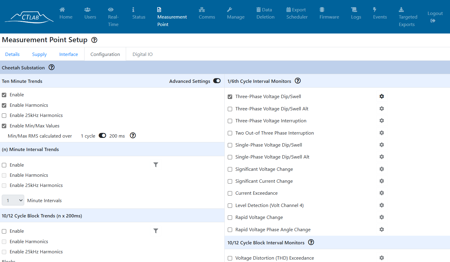
The default configuration is set to the NRS048 (South African Quality of Supply) directive. The configuration can be left on default. Otherwise select all the required data streams and monitors to be activated in this window.
Click the "Next" button when done.
¶ Step 7: Digital IO
If you have Digital IO channels connected to the instrument they can be setup here. This is an advanced feature and see the VECTO3 user manual for further details.
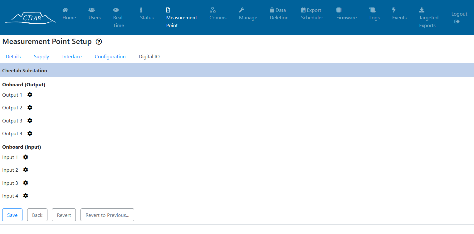
Click the "Next" button when done.
¶ Step 8: Save the Measurement Point Configuration
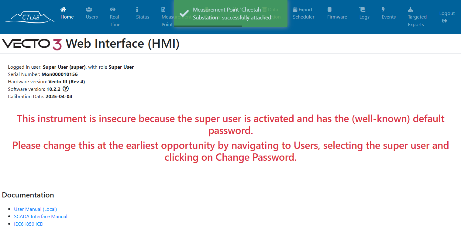
Click the "Save" button when done.
¶ Step 9: Real-Time View
View the real-time view by clicking the "Real-Time" tab on top of the screen to view the real-time view and verify that the voltage, current, power, and phasors are correct according to expectation.
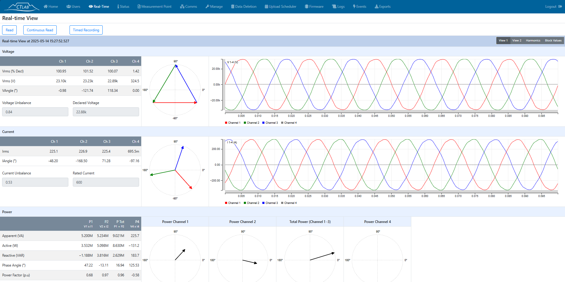
The measurement point setup is now complete from the HMI.