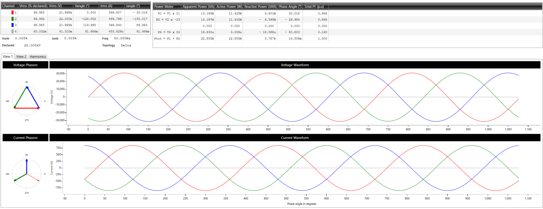
A new measurement point can only be created by Osprey Lite on an online instrument (i.e. an instrument to which a connection was established).
To create a measurement point in Osprey Lite follow the steps below:
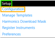
¶ Step 1: Select Setup → Configuration: Meter Point
¶ Step 2: Create Measurement Point
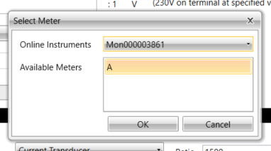
Click Create at the bottom of the meter point selection panel and select the instrument on which you would like to create the measurement point. Measurement points can only be created on online instruments.
¶ Step 3: Enter Measurement Point Details
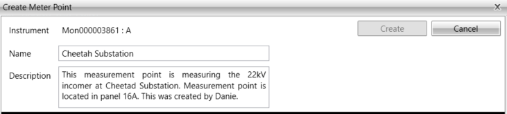
- Select a name for your measurement point, this name must be unique across all meters.
- Add a description to the measurement point.
Useful information to possibly add in the description:
- Where is the measurement point located?
- What is it connected to?
- Who created the measurement point?
- When was the measurement point created?
¶ Step 4: Enter Voltage Channel Details
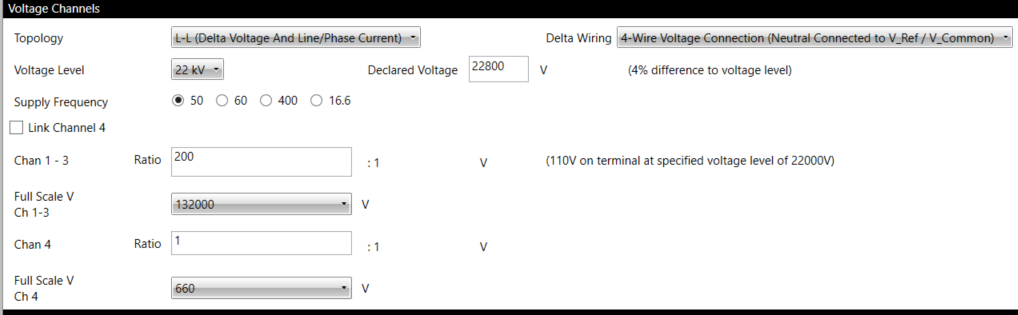
¶ Step 4.1: Select your Network Topology
This is the type of topology you want to measure in and record, it influences the expected declared voltage and energy measurement methods.
If you have a "delta" wiring topology (3-Wire) then you must choose "L-L (Delta Voltage And Line/Phase Current)".
If you have a 4-Wire systems (with a neutral conductor connected to the reference input) then you can either choose "3 Phase L-L (Delta)" or "3 Phase L-N (Star/Wye)"
See the Installation Guide for further details on the two types of voltage installation topologies.
¶ Step 4.2: Select your Voltage Level
The nominal voltage level of your network. Voltage level is always given in delta format (e.g. 400V, not 230V).
¶ Step 4.3: Select the Declared Voltage
This is the declared (contractually agreed) voltage of your system.
¶ Step 4.4: Select the Frequency
Nominal frequency of your network.
¶ Step 4.5: Link CHannel 4
If Link Channel 4 is ticked, the fourth channel will be assumed to have the same measurement interface as channels 1 to 3.
¶ Step 4.6: Enter your VT Ratio
This is the ratio of any VT connected to the voltage inputs.
Ex: 22kV:110V is equal to 200V:1V
¶ Step 4.7: Select the Full Scale Voltage
This is the highest voltage that can be represented on that channel after VT scaling, this value should be be larger than the nominal/declared voltage in order to present voltage spikes.
Note: The full scale value can only be set on the VECTO 3.4
¶ Step 5: Enter Current Channel Details
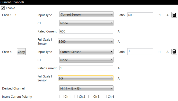
¶ Step 5.1: Tick Enable
Tick Enable under Current Channels to measure current related parameters.
¶ Step 5.2: Select Current Input Type
The Input Type selection selects which current inputs are used on the instrument.
Select whether the current is measured using transducers or directly with the instrument using its built in current sensors.
¶ Step 5.3:Select the Current Transformer Ratio
This is the ratio of any CT connected to the Current Inputs.
A helper calculator is provided to calculate serial CTs.
¶ Step 5.4 Specify Transducer model
This option is only available when you chose to measured your current using transducers. You have the option to specify the transducer model to apply a harmonic compensation curve to compensate for some non-linearity. This is optional and if you are using a transducer which is not on the list, leave the field on "None".
¶ Step 5.5: Select the Rated Current
This is the rated current of your system.
¶ Step 5.6: Select the Full Scale Current value (If you selected to measure current using Current Sensors)
This is the highest current value that can be represented on the channel after CT scaling.
¶ Step 5.7: Select the Full scale Voltage value (If you selected to measure current using Current Transducers)
This is the highest voltage value that can be represented on that channel after VT scaling.
¶ Step 5.8: Select if you are Deriving any Channels
If you are using a delta system, either of the three channels can be derived from any of the other two.
¶ Step 5.9: Select if any Current Polarity
If you have inverted currents it can be corrected in software by selecting the relevant channels here.
¶ Step 6: Create Measurement Point
Click Create to create the meter point.
The measurement point is now mounted and recording.
Meter point creation occurs on the instrument. If communications fail during creation, Osprey Lite will not insert the meter point into its database.
¶ Step 7: Ensure that the Installation and Configuration is Correct
Select Communication → Real-time View then Continous Read to inspect that the Real Time View of the voltage and current readings match in phase and magnitude according to expectation for the measurement point.
Ensure that the correct measurement point is selected in the top left corner.