¶ Introduction
Welcome to the installation guide of the VECTO 3.4. This page provides comprehensive instructions and information on the installation of the VECTO 3.4. This guide will walk you through each step, from mounting and power connections to configuring communication and input parameters. By following these guidelines, you will ensure that your VECTO instrument is installed correctly and ready to deliver precise power quality measurements.
¶ Downloadable Documents
VECTO 3.4 Data Sheet
VECTO 3.4 User Manual
VECTO 3.4 Quick Start Guide
¶ Pre-Installation Requirements
¶ 🪛 Tools
See below a list of possible tools that might be needed for a successful installation of the VECTO 3.4 device.
- Flat Screw Driver (2mm)
- Wire Stripper
- Lugs
- Crimper
¶ 📅 Planning
Before installing the instrument, it's crucial to plan thoroughly to ensure a smooth and successful installation. Here are some points to consider before the installation:
¶ ❓ What do you want to measure?
Make sure you know what the measurement objectives are. This will determine the installation and configuration requirements for the entire installation.
¶ 🔌 How would you supply power to the instrument?
The instrument needs a reliable power source to operate continuously. Identify the power source that would be used.
Ensure the power source is stable and within the instrument’s input range:
- AC Input Voltage Range: 90 V - 300 VAC (42 - 65 Hz)
- DC Input Voltage Range: 90 V - 280 VDC
Note: Avoid overloading VT circuits if powering from the same source.
¶ 🔄 How would you measure current?
The current can be measured either directly with the instrument or by using current sensors (transducers). The choice is made based on the installation environment and accuracy needed.
It is also important to know what the CT ratio is, if there are any.
Option 1: Direct Current Measurement
This option is more accurate but could be more dangerous and close care must be taken when working with the instrument. 2-port terminals must be installed to short the CTs before removing the connector block.
This method is generally recommended when the data will be used for billing verification and very high accuracy is required.
- AC Input Current Range: 0 - 8 AAC
- Maximum DC Input Current: 11 ADC
Option 2: Current Sensor Inputs (Transducers)
This option is safer but slightly less accurate. With revenue grade transducers the error could be about 2% but can be about 1% if you are measuring near unity power factor.
This option is usually recommended for general use.
- Measurement Input Range: ±2.5 VRMS, ±3.6 VDC
¶ ⚡ How would you like to measure voltage?
What is the:
- Source
- Topology? Three-phase star / delta?
- Voltage level?
- Declared voltage?
- VT ratio, if any?
Consider using fuses for protection. Ensure correct phasing and polarity to avoid incorrect readings.
Voltage Input Limit:
- Line to Neutral Voltage Limit: 600 VACL-N
- Line to Line Voltage Limit: 1000 VACL-L
- DC Voltage: ±850 VDC
Examples:
Measure main incomer on 66kV: Typically in substations. VT (voltage transformer) and CT (current transformer) inputs are required. Choose to measure current with current trasducers. The substation does have backup DC available to power the instrument and space on the DIN rail for the instrument.
Machine load at 400V: Low voltage installations with voltage below the maximum range of the instrument allow for direct connection and voltage measurement. Direct current measurements will be required in these installations and the use of Rogowski Coils or higher rated (50/100/250A) clamp on current sensors are recommended.
¶ 📡 GPS Installation
GPS is essential for time synchronization across multiple instruments. The GPS antenna requires a clear sky view, outside or near a window. Consider cable routing or the use of extension cables (up to 100m total length).
¶ 🌐 Communication
Plan how the instrument will communicate with your data platform (ethernet / cellular / none). Some installation of Cellular antenna or ethernet cabling might be required.
¶ 📐 Mounting/Dimensions
This section will cover the physical dimentions and mounting of the instrument.
¶ Physical Dimensions
Consider the pysical dimensions of the device during installation.
If you will need access to the USB port or the SFP cage, do consider that they are located on the right side of the instrument.
If transducers will be used, note that they connect to the left side of the instrument, and depending on the wire type some extra space on the left hand side might be needed.
Pysical Dimensions:
Width: 245 mm
Hight: 125mm
Depth: ~77mm.

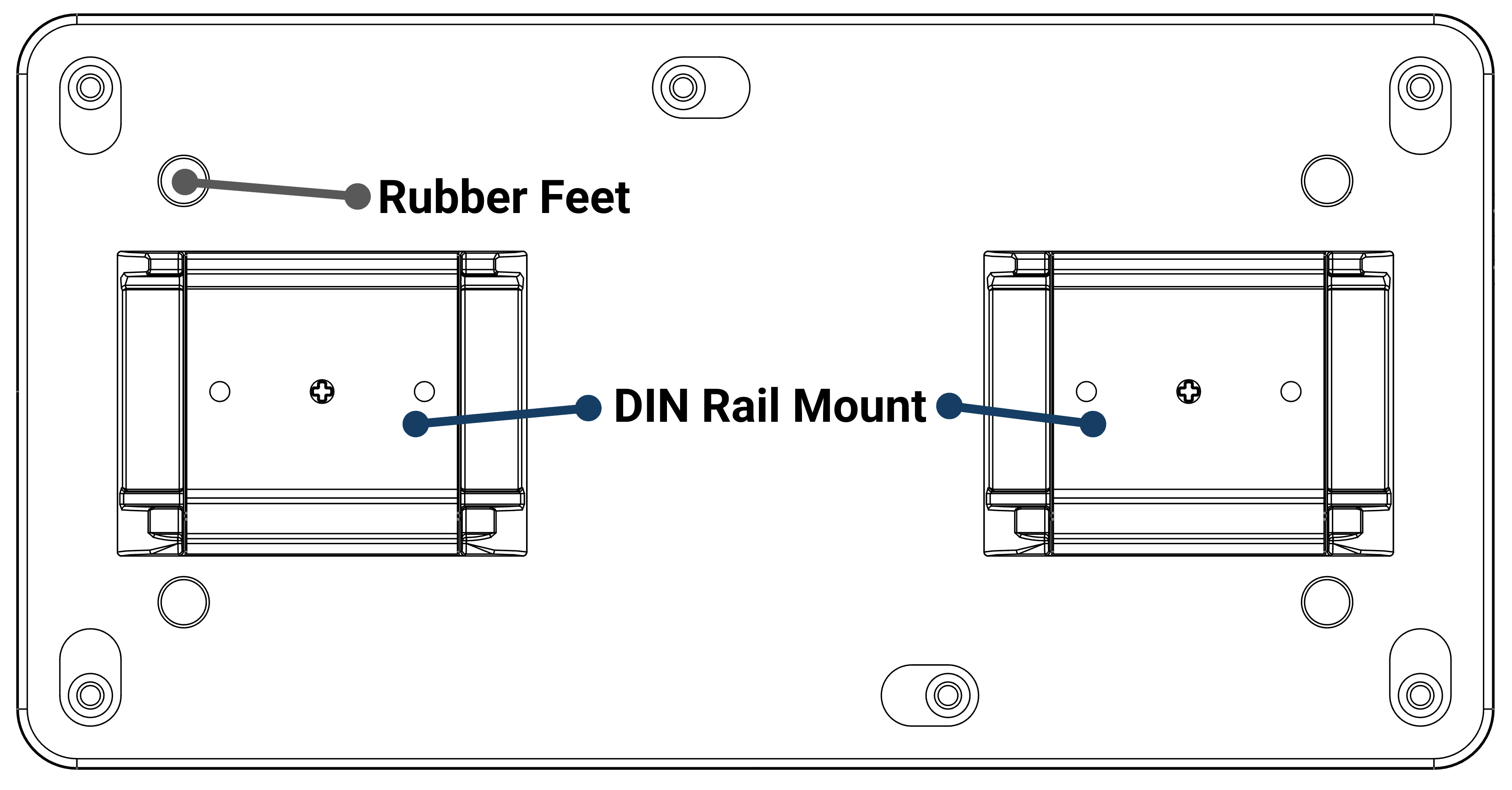
¶ Mounting Options
There are two mounting options available for the VECTO 3.4. The device can be mounted in any orientation.
-
Flat on rubber feet, this is commonly used for temporary installations.
-
DIN rail mount. The DIN rail mounts can be screwed on and the instrument mounted to a DIN rail.
On newer instrument versions: flip the instrument and unscrew the back two plates. Flip these two plates to reveal the DIN rails.
¶ Power Supply and Earth
The instrument needs a reliable power source to operate continuously.
The instrument can either be powered from the mains connector (with AC or DC) or with Power Over Ethernet (POE) from any of the two ethernet connectors. Ensure the power source is stable and within the instrument’s input range which is spesified below.
Remember to always connect the safety earths first.
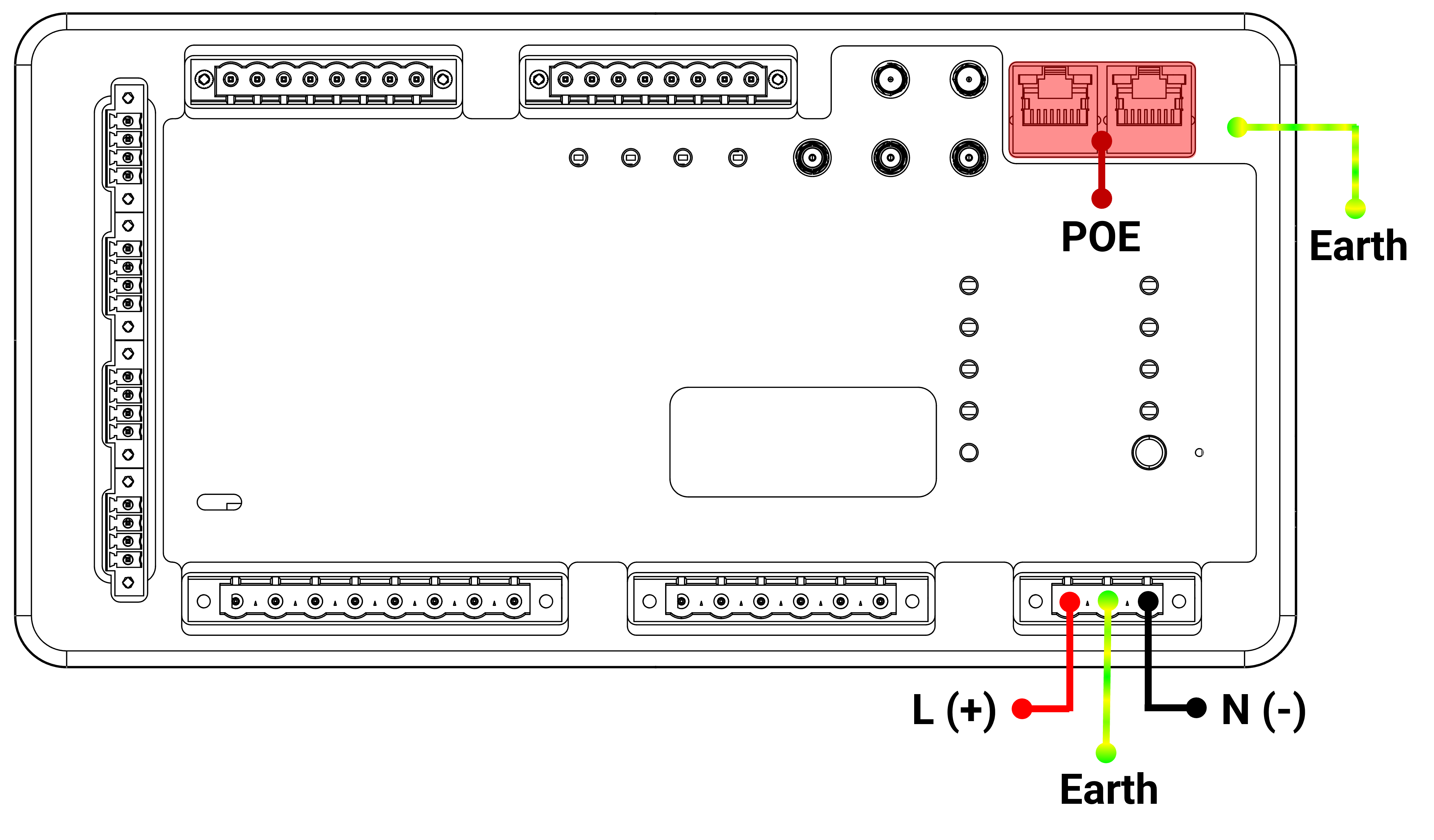
| Power Intput Specifications: - POE+ Support (IEEE802.3at) on both ethernet ports - AC Input Voltage Range: 90V - 300VAC (42–65Hz) - DC Input Voltage Range: 90V - 280VDC - Power Draw: 20VA (max) - Backup Battery for 5 min (user adjustable) |
If external power is present the EXT Power LED will be lit.
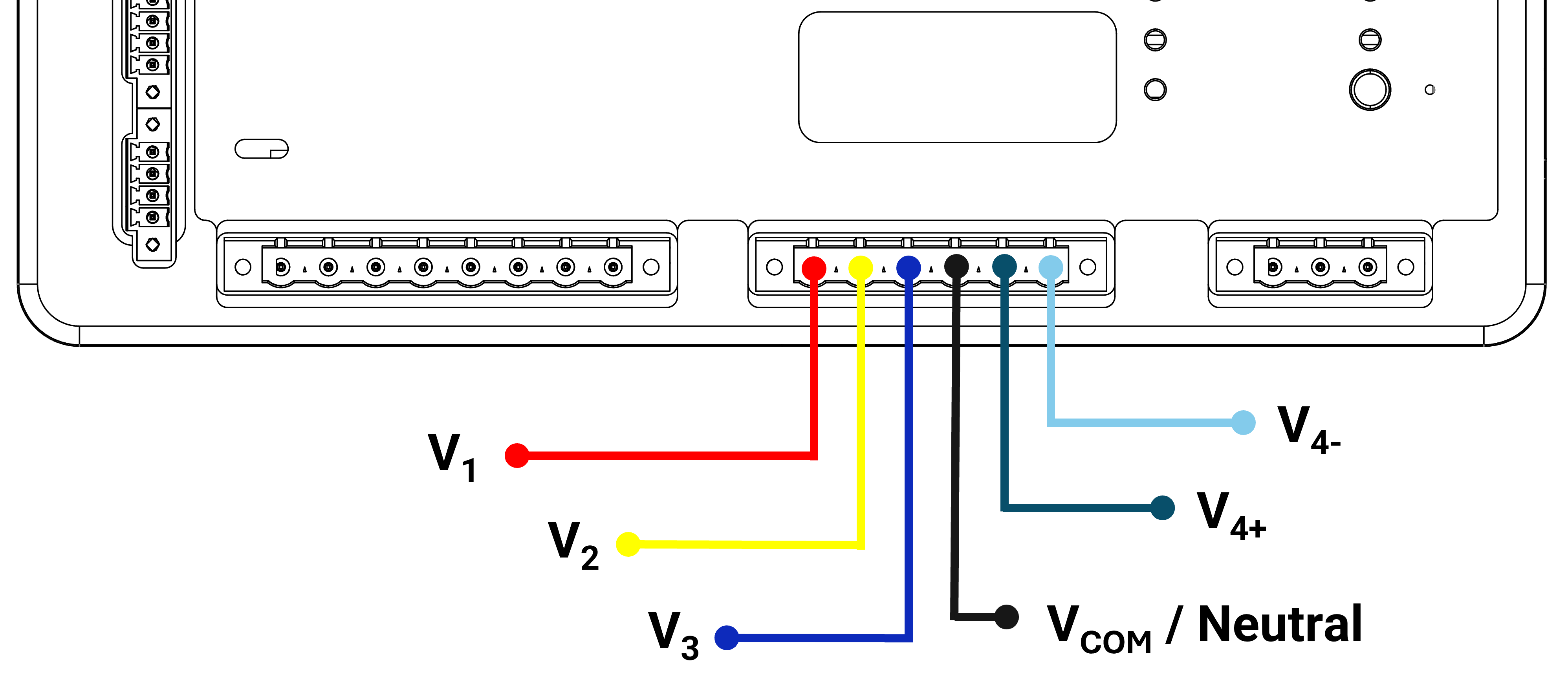
¶ Voltage Inputs
| Voltage Input Specifications: - Line to Neutral voltage limit: 600VACL-N - Line to Line voltage limit: 1000VACL-L - DC Voltage: ±850VDC |
Voltage Input Information: - High Impedance Inputs (with floating reference) - Fully Differential Measurement - 4th Auxiliary channel availbale for extra use |
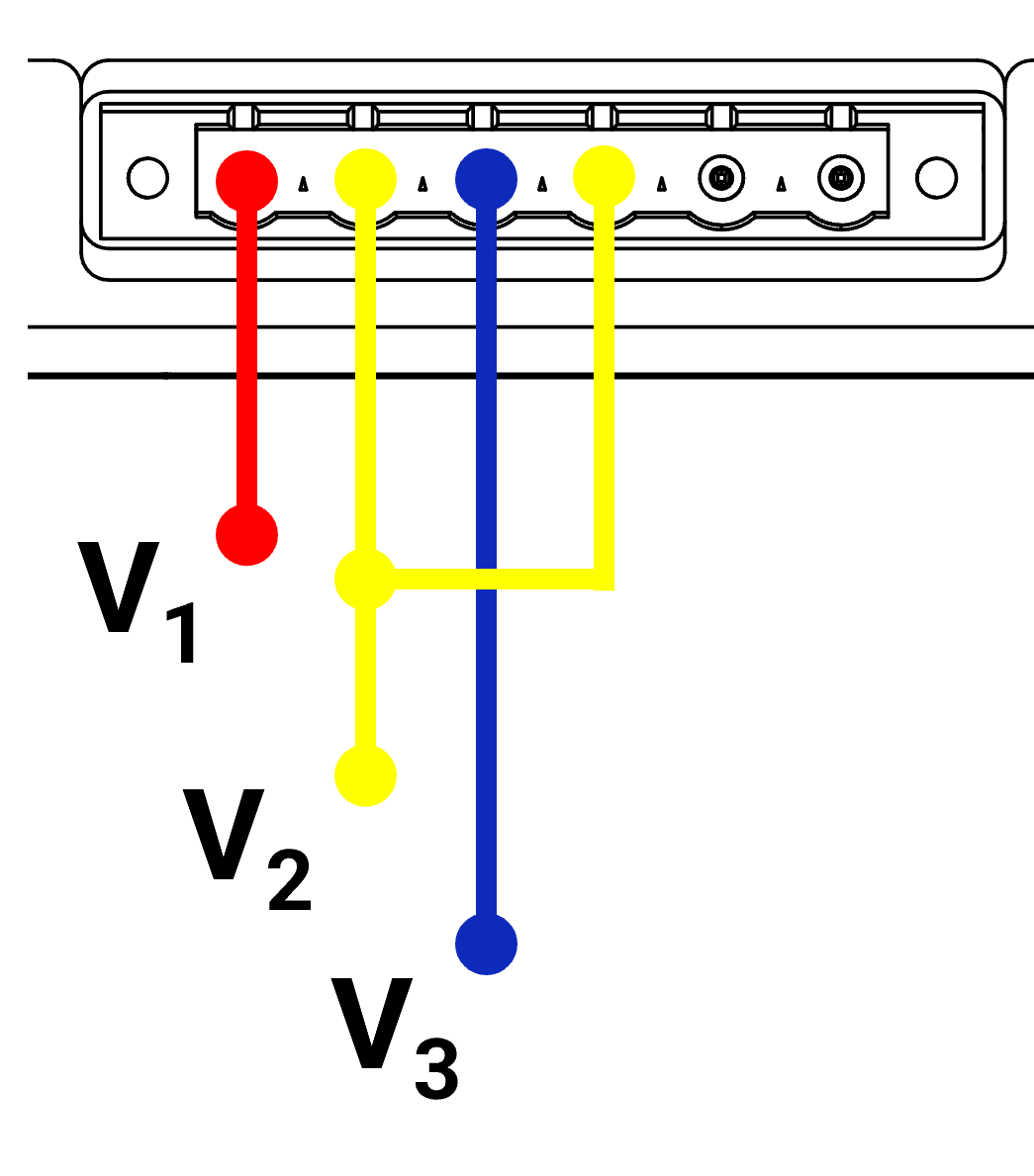
¶ Voltage Connection Topologies
| Delta Connection | Star (WYE) Connection |
|---|---|
|

|
¶ Current Inputs
Choose the right current measurement method based on the installation environment.
Optional Options:
- Derive 3rd current from 2x inputs (Delta Connection)
- Derive 4th current from 3x inputs
¶ Option 1: Direct Current Inputs
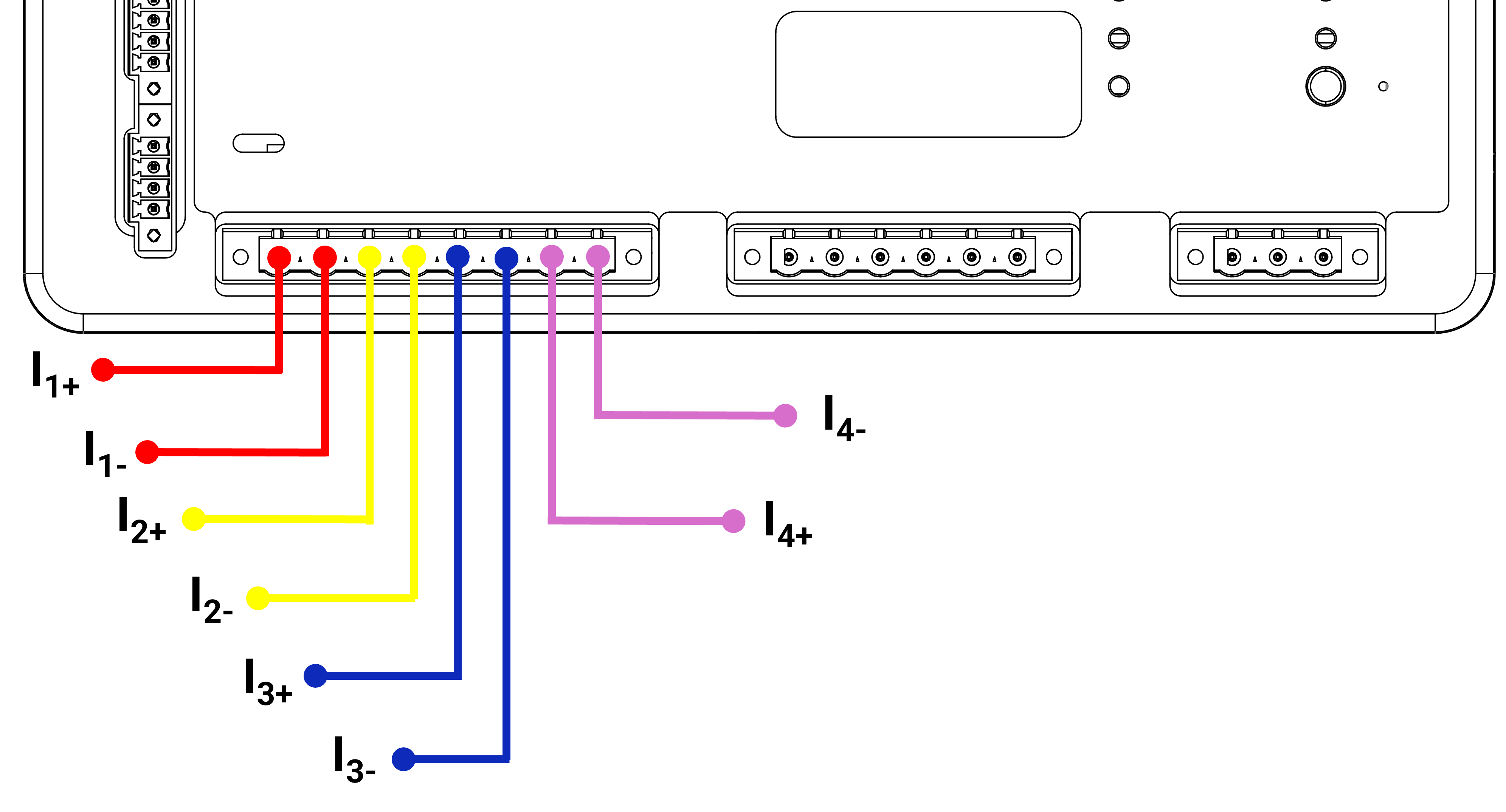
With direct current inputs, the currents are dicrectly routed through the instrument for measurement. This is the standard method used for metering.
| Current Input Specifications: -Input Range AC: 0-8AAC - Input Range DC: ±11ADC |
Current Input Information: - Galvanically Isolated Current Inputs - For 1 Second Withstand: 50A |
This terminal must be screwed in properly!
Remember to short current channels before removing the terminal!
¶ Option 2: Current Sensor Inputs (Transducers)
 |
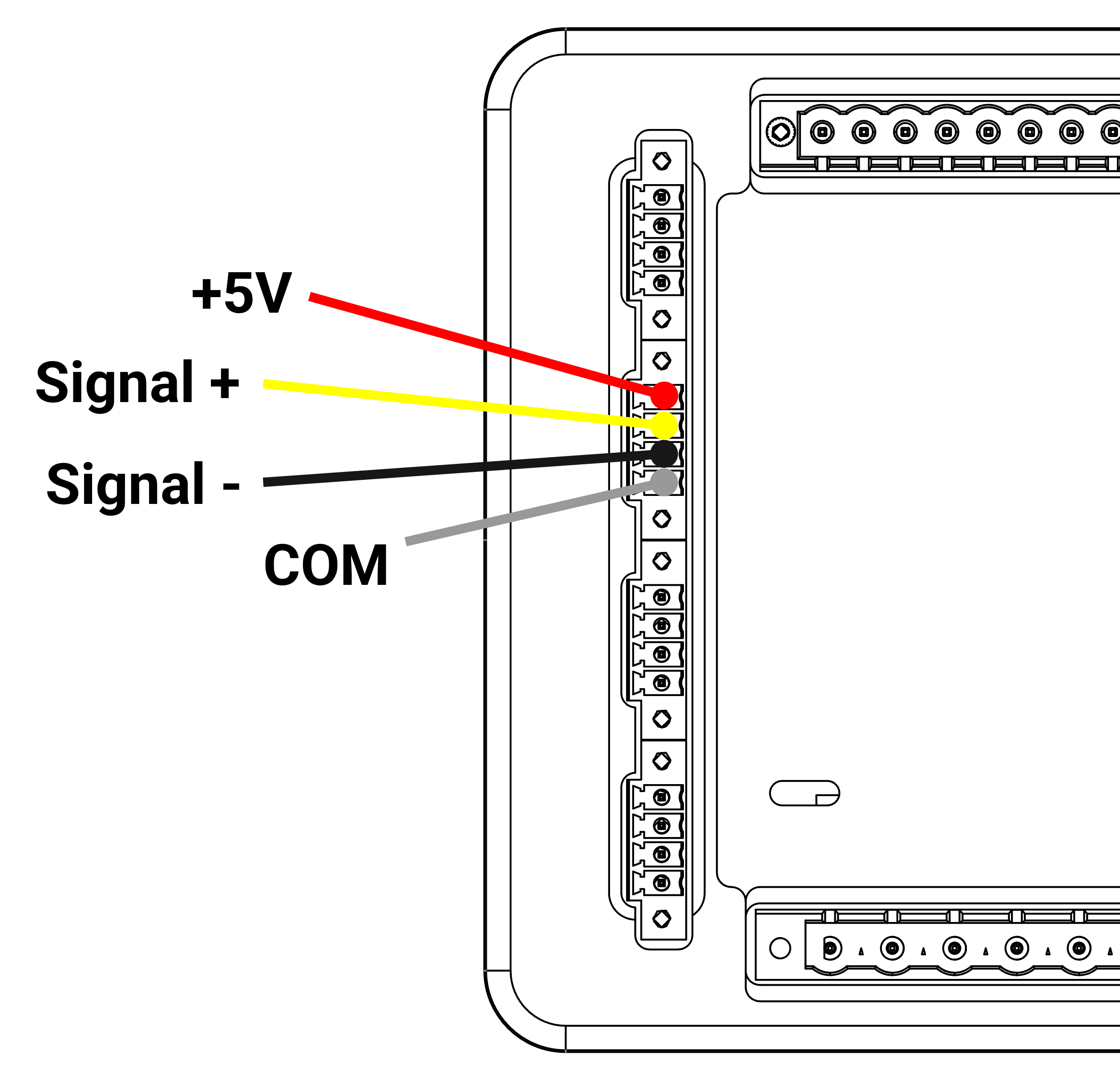 |
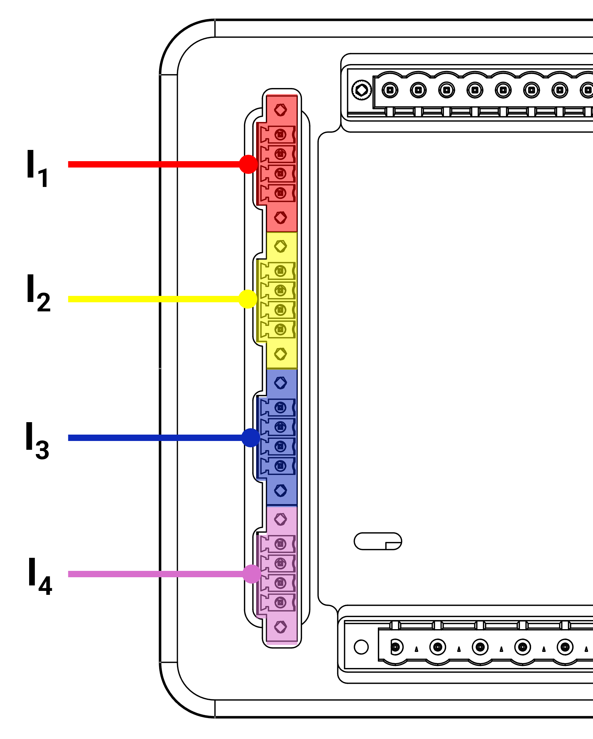
Using a screened twisted pair for wiring between the transducer and the VECTO 3.4 will maximise performance and reduce noise.
Note: Neutral current can be derived from the three measured currents.
¶ Connect the GPS (highly recommended)
Connect the GPS directly or via the extension cable to the GPS SMA connector on top of the instrument next to the ethernet ports.
Make sure that the GPS antenna has a predominantly clear sky view.

- The GPS is needed to measure time(<100ns time accuracy)
- Maximum of 100m extension for the GPS
¶ Cellular Antenna and SIM (optional)

- Connect the cellular whip antenna to the Cellular Main port.
- Optionally - Connect a MIMO antenna to the Cellular Main and DIV ports.
- Insert SIM card on the right side of the device.
- For communications setup, please see the VECTO 3 manual.
Add VECTO 3 manual. Max is currently 5MB, file is almost 10MB, increase limit.
Make sure that the SMA connector(s) are properly screwed in..
¶ Wiring Diagrams
3-Wire (Delta) with Current Inputs and DC/AC Supply
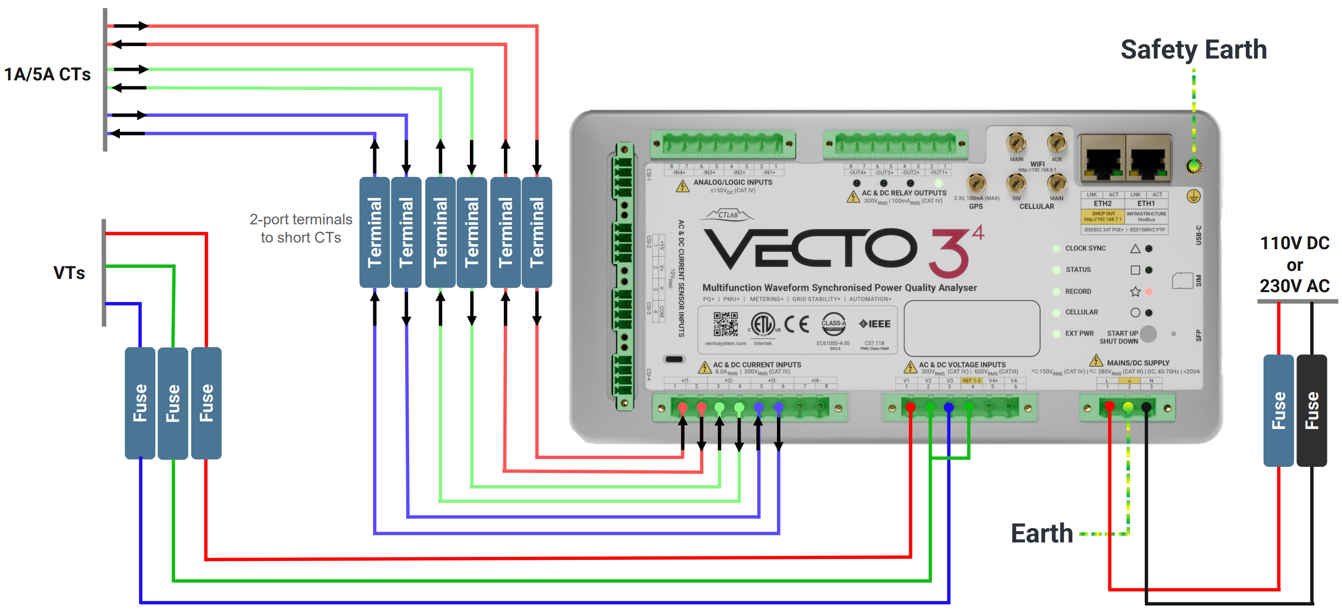
3-Wire (Delta) with Current Transducers and DC/AC Supply
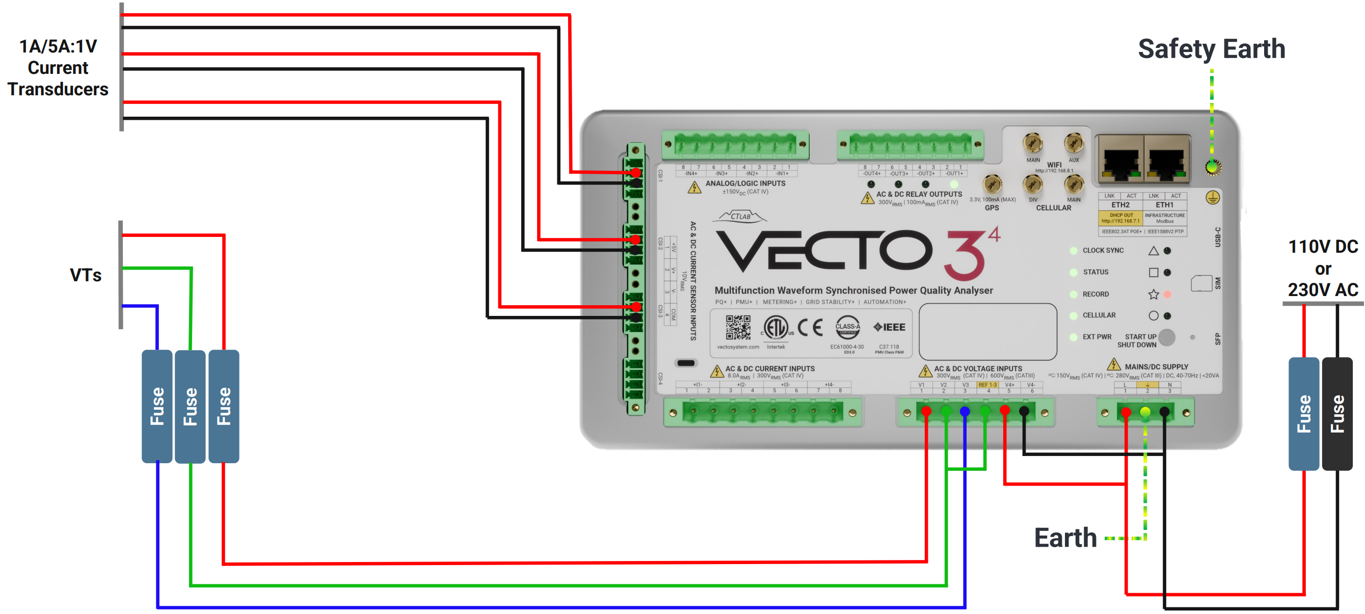
4-Wire (Star) with Current Inputs and powered with POE
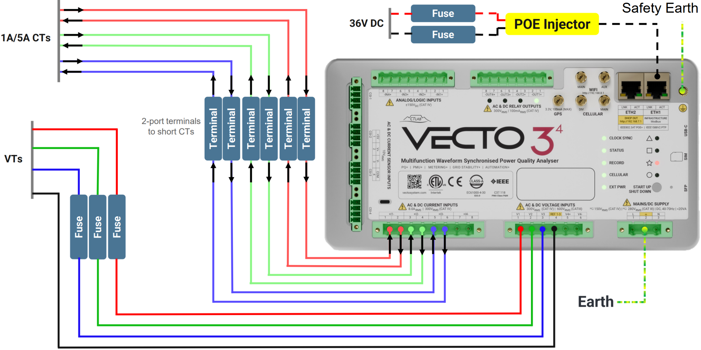
4-Wire (Star) with Current Transducers and powered with POE
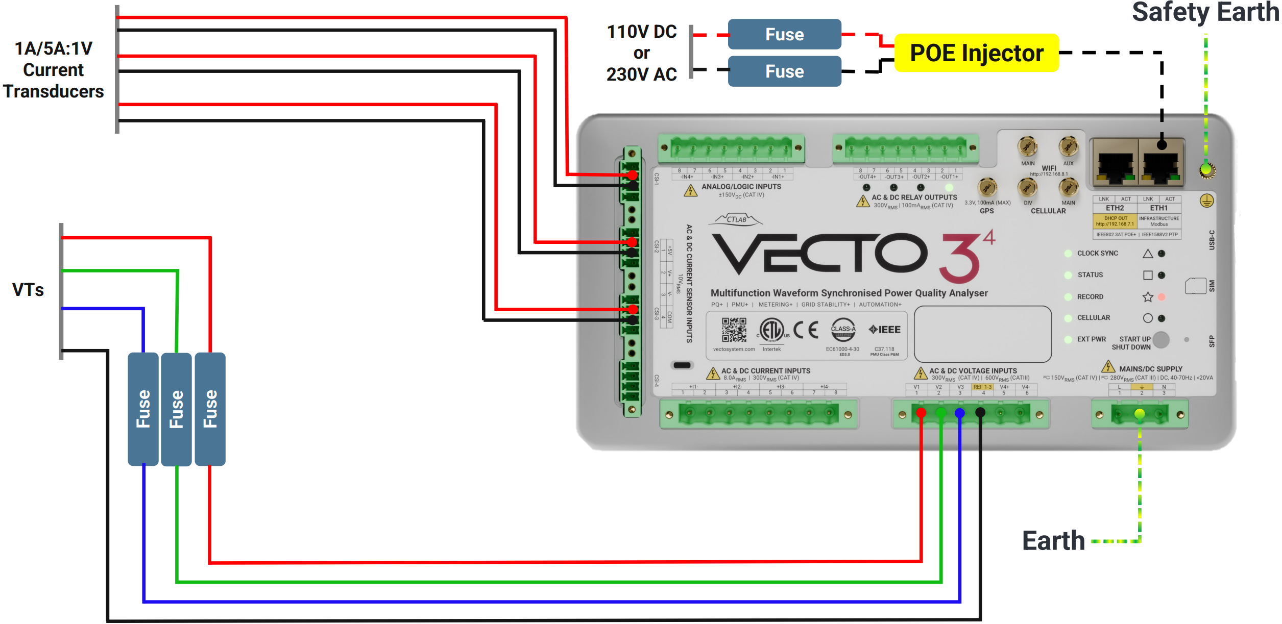
¶ Inputs and Outputs
¶ Analog/Logic Inputs:
These inputs can be used to trigger a monitor.
- 4x Inputs
- ± 150VDC (max)

¶ Relay Outputs:
These outputs can be used to trigger a monitor.
- 4x Relay Outputs
- AC Input Voltage Range: 300VAC (max)
- DC Input Voltage Range: 100mAAC (max)

¶ Power On
- Power up the VECTO 3 by holding the power button down until the instrument starts booting and the STATUS LED starts flashing orange.
- When the STATUS LED turns green the instrument is booted and running.
Exercise caution with the button; avoid using excessive force.
¶ Complete Installation
After Physical installation is complete: