The measurement point Setup for VGOS are very similar to the setup for the HMI.
¶ Step 1: Add New Measurement Point
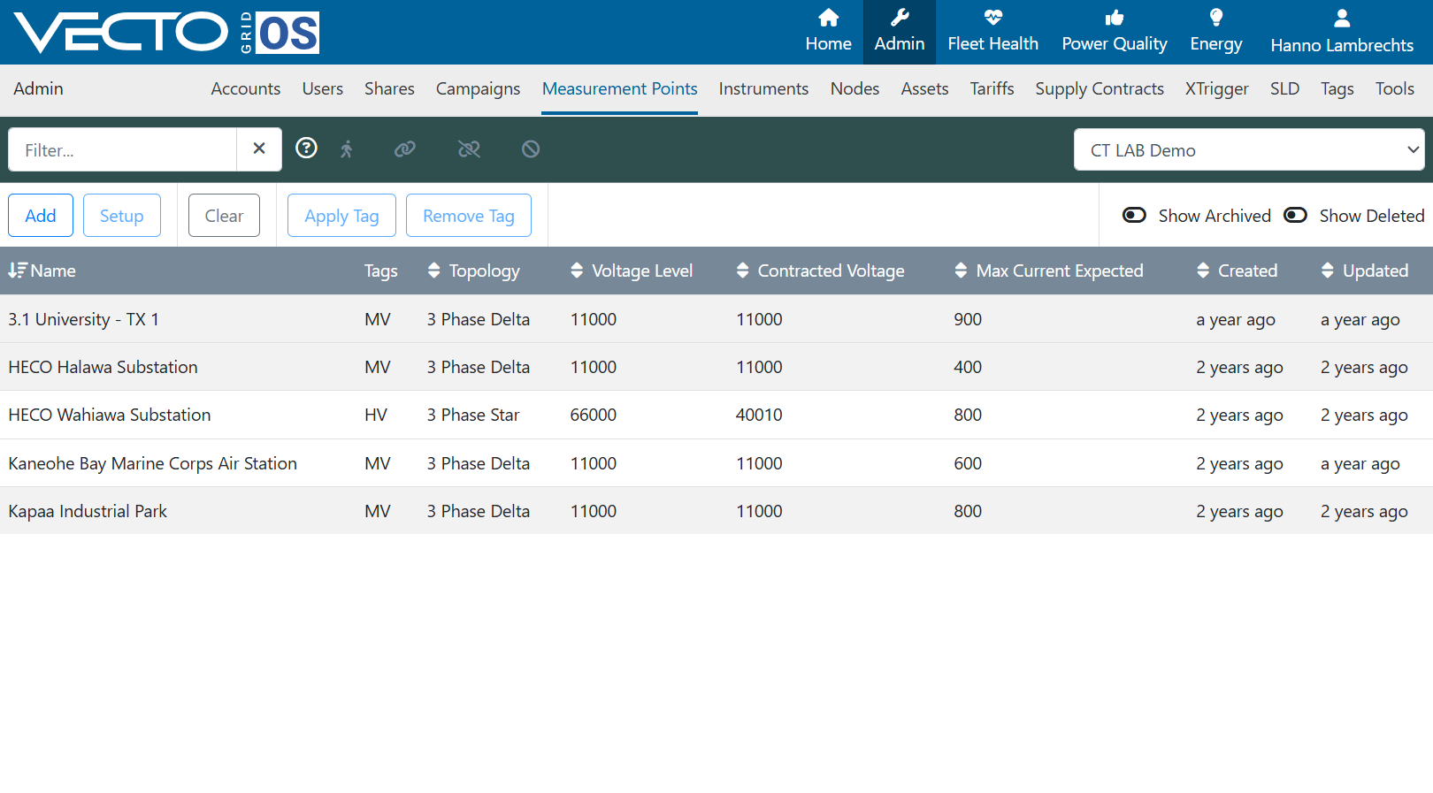
To add a new measurement point on VGOS, navigate to the "Admin" main tab and the "Measurement Points" sub-tab. Here all of the measurement points on your account will be listed. Note that even detached/decommissioned measurement points will be listed here. To create a new measurement point, click the "Add" button in the top left section of the window.
¶ Step 2: Details Section
-
Select a Name for Your Measurement Point
-
Enter a Description for the Measurement Point
-
Enter notes about the installation
These fields is especially useful for documentation, collaboration, and audits. GPS coordinates will automatically be populated later once the instrument is online with a connected GPS.
If "Is Manually Configured" Flag is set it implies the measurement point is managed externally to VECTO Grid OS (e.g. by Osprey Lite). VECTO Grid OS will not change this measurement point's configuration.
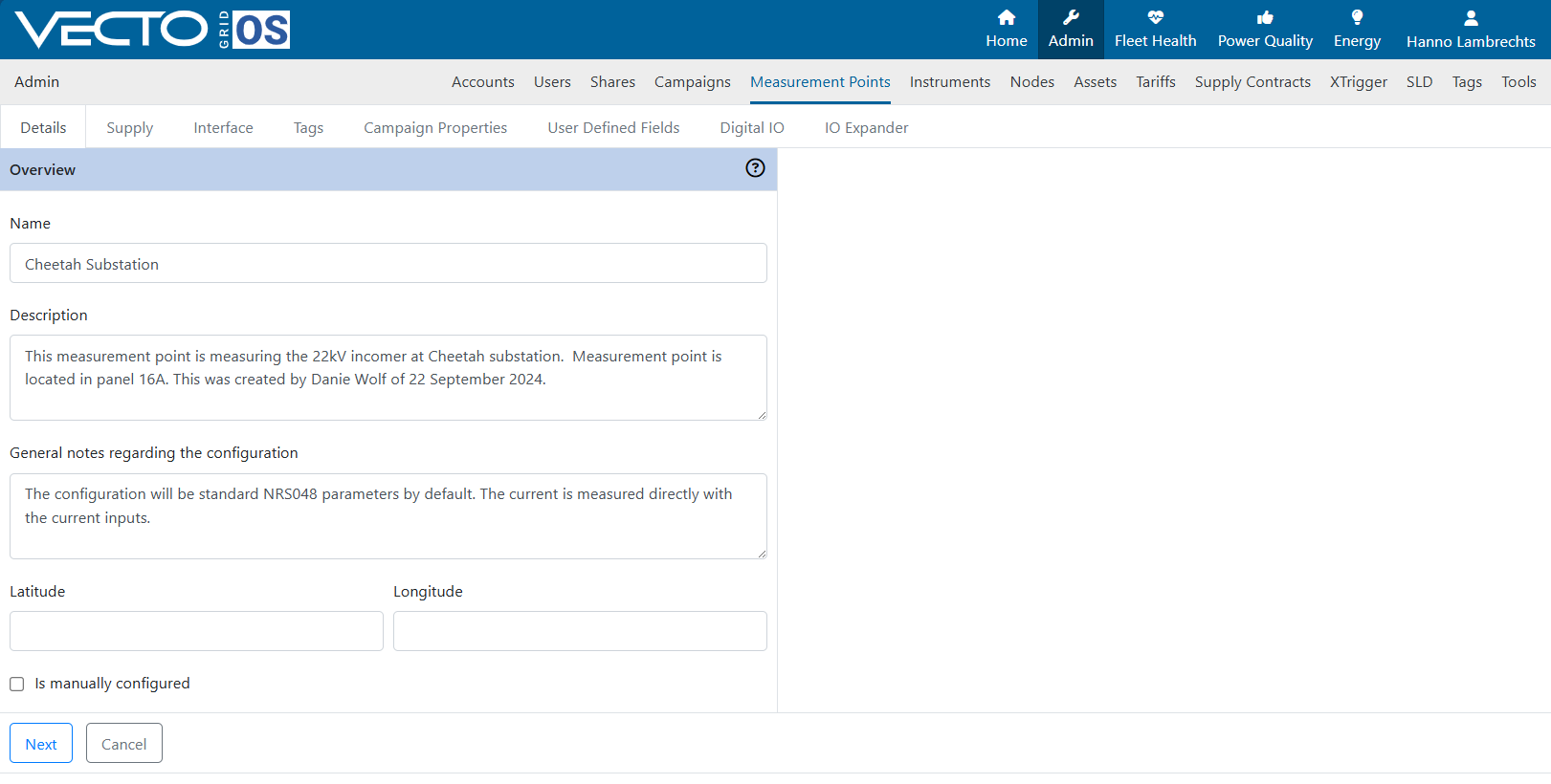
Click the "Next" button when done.
¶ Step 3: Supply Section
Follow the sub-steps below to enter all the required details of the supply section of the measurement point.
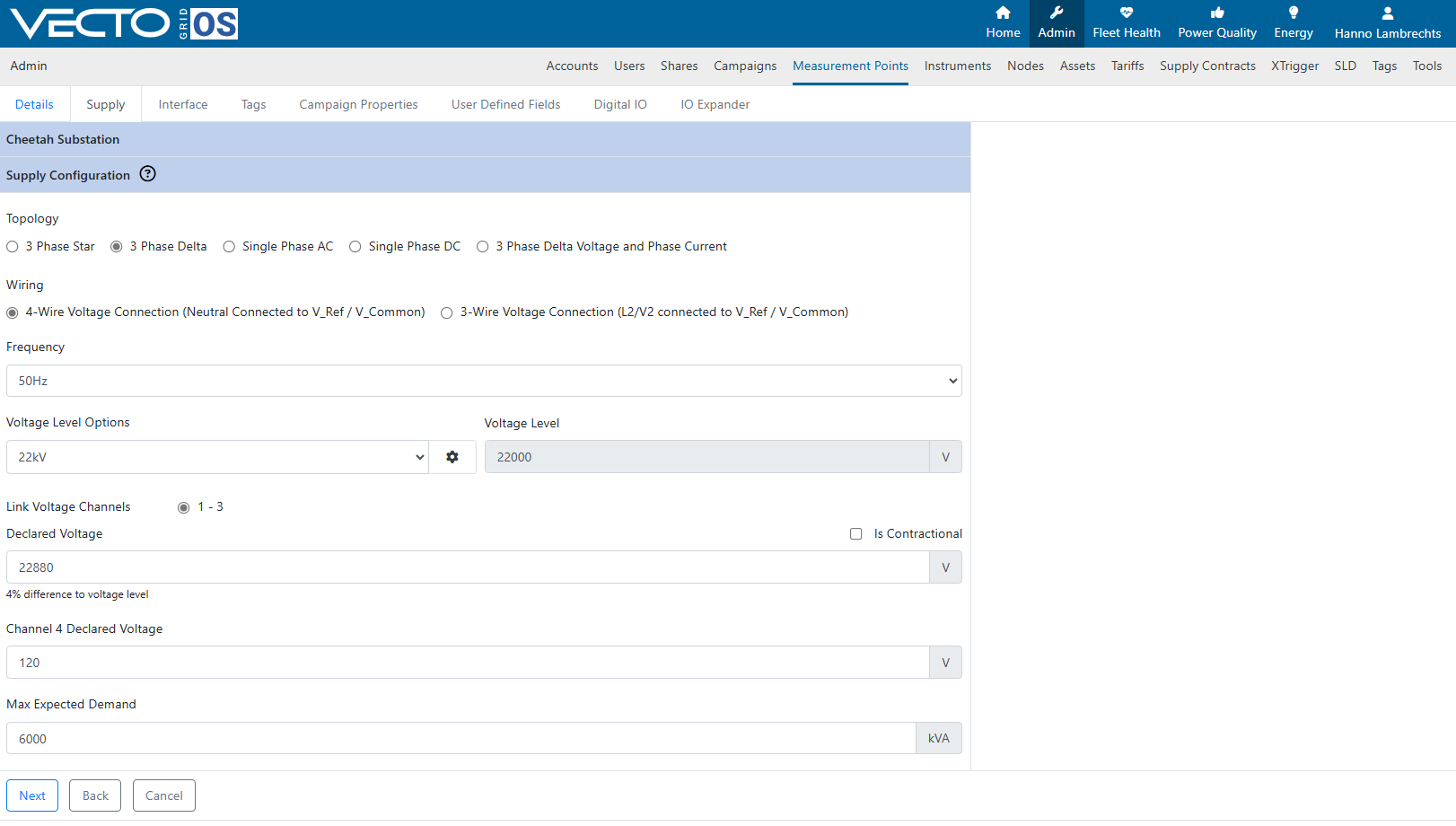
Step 3.1: Select your network typology
This is the type of topology you want to measure in and record. If you have a "delta" wiring topology (3-Wire) then you must choose "3 Phase L-L (Delta)".
If you have a 4-Wire systems (with a neutral conductor connected to the reference input) then you can either choose "3 Phase L-L (Delta)" or "3 Phase L-N (Star/Wye)"
See the Installation Guide for further details on the two types of voltage installation topologies.
Step 3.2: Select your wiring topology
This is how you installed your measurement point. Again, see the Installation Guide for further details on the two types of voltage installation topologies.
Step 3.3: Select your frequency
Nominal frequency of your network.
Step 3.4: Select your voltage level
The nominal voltage level of your network. Voltage level is always given in delta format (e.g. 400V, not 230V).
Step 3.5: Select the declared voltage
This is the declared (contractually agreed) voltage of your system.
Step 3.6: Add your Maximum Expected Demand
This field is optional
Click the "Next" button when done.
¶ Step 4: Voltage Measurement Interface Parameters
Follow the sub-steps below to enter all the required details of the interface section of the measurement point.
Step 4.1: Enter your VT Ratio
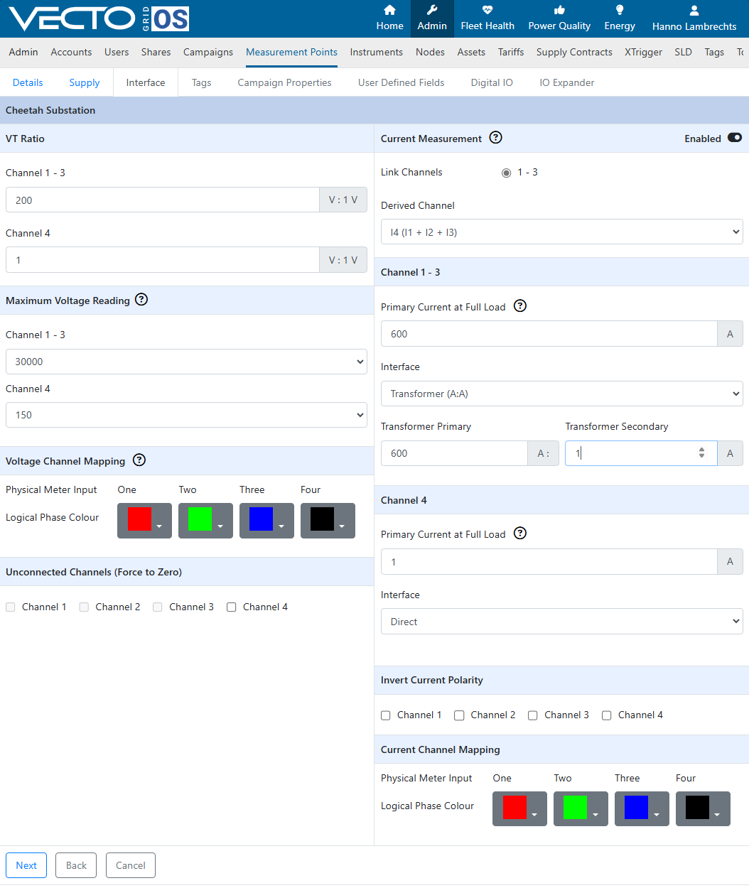
This is the ratio of any VT connected to the voltage inputs.
Ex: 22kV:110V is equal to 200V:1V
Step 4.2: Select the maximum voltage that will be measured
Select the maximum voltage in RMS that will be measured to optimize the dynamic range of the measurement.
Step 4.3: Change the voltage channel mapping
Only change this settings if it is really necessary and you fully understand what this means.
Step 4.4: Mark if there are any unconnected channels
This setting will force the respective channel to 0 and ensure that no floating voltage is measured.
Click the "Next" button when done.
¶ Step 5: Current Measurement Interface Parameters
Follow the sub-steps below to set the current interface parameters.
Step 5.1: Select if you are deriving any channels
If you are using a delta system, either of the three channels can be derived from any of the other two.
Step 5.2: Enter the primary current at full load
Used to calculate Total Demand Distortion (TDD) and % full scale current.
Step 5.3: Choose current measurement interface
Current Connection Interface Topologies:
- Transformer (A:A)
- Transducer (A:V)
- Transformer into Transducer (A:A > A:V)
If you have chosen one of the two options with a transducer, you have the option to specify the transducer model to apply a harmonic compensation curve to compensate for some non-linearity. This is optional and if you are using a transducer which is not on the list, leave the field on "uncompensated".
Step 5.4: Choose Maximum Current Reading
Select the maximum current in RMS that will be measured to optimize the dynamic range of the measurement.
Step 5.5: Select Current Polarity
If you have inverted currents it can be corrected in software by selecting the relevant channels here.
Step 5.6: Change the current channel mapping
Only change this settings if it is really necessary and you fully understand what this means.
Click the "Next" button when done.
¶ Step 6: Apply Tags
Apply any tags to the measurement points. Tags are used throughout the system to group items. For example, a investigation campaign may be applied to measurement points taged with "Investigate".
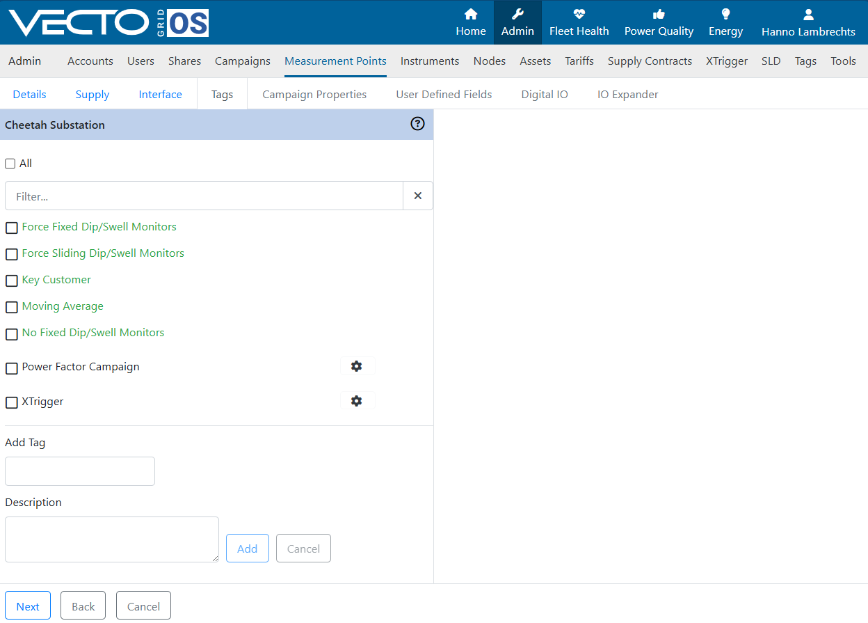
Click the "Next" button when done.
¶ Step 7: Add Custom Contratual Levels
A measurement point can be part of a supply contract configured under Admin → Supply Points. If it is not part of a supply contract, but has an individual contract, select "Has it's own contract". The contract details can then be specified in this section.
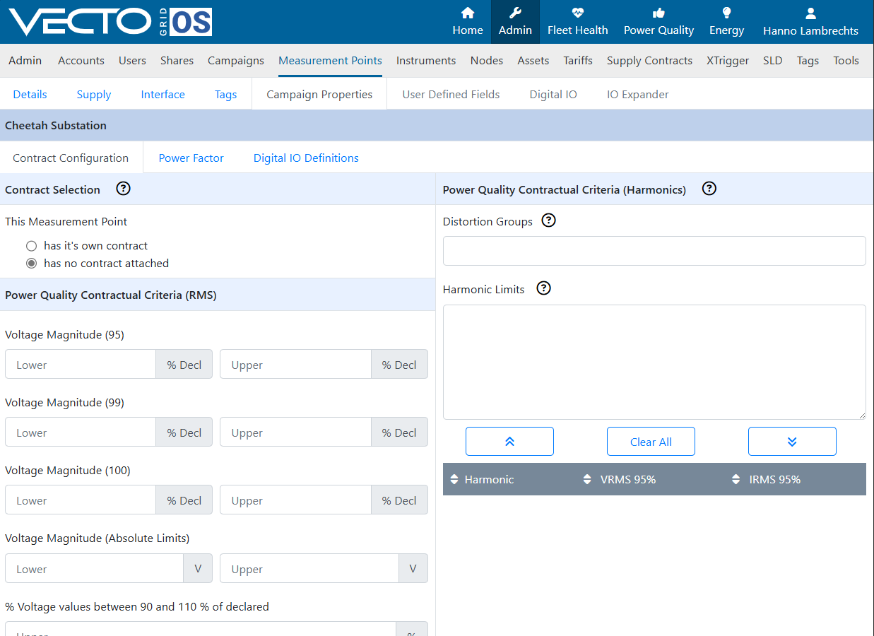
Click the "Next" button when done.
¶ Step 8: Add User Defined Fields
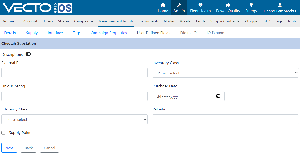
This is an advanced option. Contact CTLAB for assistance if you want to create user defined data field for the measurement points. If not, you can just skip this step.
¶ Step 9: Configure Digital IO
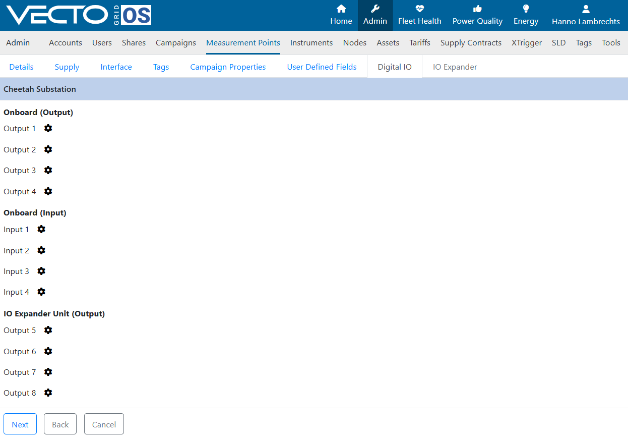
Setup any digital IO configurations. This is also an advanced options and if you are not using the digital IO inputs or outputs, you can skip this step.
¶ Step 10: Skip IO Expander
Skip the page on IO Expander setup and click the "Save" button to create and save the new measurement point.
¶ Step 11: Save Measurement Point
Click "Save
¶ Step 12: Attached Measurement Point to Instrument
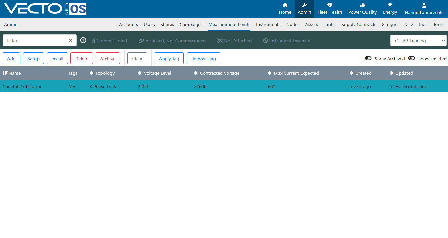
Click on your new measurement point to select it. The measurement point will be highlighted in an eastern blue color.
With your measurement point selected, click the “Install” button.
¶ Step 13: Choose Instrument
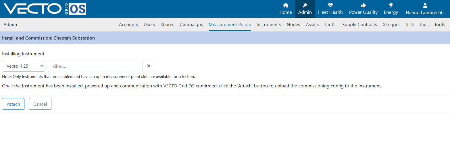
In the dropdown list choose your available instrument to which the measurement point will be attached. Note that only instrument which are enabled and does not have any measurement point attached will be shown.
With your instrument selected, click the “Attach” button.
¶ Step 14: Complete Installation
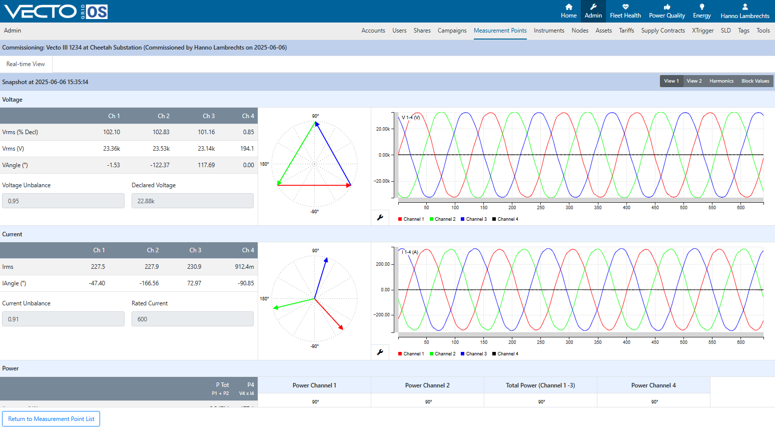
Inspect that the Real Time View of the voltage and current readings match in phase and magnitude according to expectation for the measurement point.
Then click the “Installation Complete” button.

Once you are happy with the real-time view and ready to start recording click the "Mark as Commissioned" button.

The measurement point is now commissioned and recording.
The measurement points is now mounted and recording. The data is being sent to VGOS every 10min and you can now proceed to analyze and visualize your data.